 Up
Up
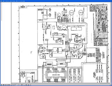
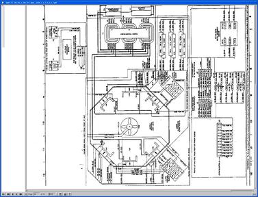
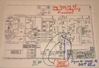
This schematic explains placement of the DC -> AC inverter inside the welder. The page that I drew on is page 66 from the Hobart CyberTig manual. If you get that PDF and enlarge that page, you would see all details. You can see pictures of the welder and its innards there.
Green lines represent DC coming into the inverter, blue lines represent AC coming out of the inverter. They all originate and terminate at the commutator.
Right now, the commutator has two positions, right for DCEP, and left for DCEN. The middle position is OFF. I will add functionality to start the inverter if the commutator switch is in the middle position.


